ELPROCAD Plan - the complete CAD solution for electrical installation drawings
For those who work with electrical installations in buildings, ELPROCAD Plan is the perfect CAD tool. Work directly on the architect’s digital floor plan, allowing you to quickly and efficiently place everything from wall outlets and lighting to data and security installations.

From floor plan to perfection

ELPROCAD Plan works directly in the standard .dwg file format without the need for conversions. The program can both read and save in the 2023 format and earlier versions. The program contains all the symbols and functions you need to draw:
- installation drawings, ductwork, power, lighting, telecom and alarm
- floor plans and overview diagrams
- single-line diagram
- main wiring diagram
- central inventory, accounting
- quantity report in Excel
- functions for drawing up simple architectural drawings.
Communication
ELPROCAD Plan gives you great freedom to move information to other programs. Drawings are compatible with other programs in the ELPROCAD family. The drawing files follow the standard format (.dwg) and can therefore be used by various CAD applications.
Operating system and hardware
ELPROCAD Plan can be used on Windows 10 (x64) and Windows 11 (x64). The program can be installed as a single license or as a floating license in networks. Available in English, Swedish and Danish language versions.
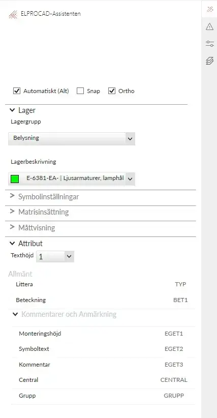
The ELPROCAD Assistant
When developing the working methodology in ELPROCAD Plan, we focused on the fact that even a person who does not draw daily should be able to use the program. The program is designed to support the user with instructions throughout the drawing process. To accomplish this, we created the ELPROCAD Assistant.
The ELPROCAD Assistant helps you to:
- View and select the type of installation you are currently drawing, such as lighting, power, telecom, alarm and more.
- View and select which installation layer the symbol should be placed on.
- View and enter information about the symbol’s designation, lettering and mounting height.
- Use dimension display with the possibility to directly enter exact dimensions.
- Choose to perform a matrix insertion by specifying number or fixed dimensions.
- Possibility to rotate the symbol, for example a cable ladder, to the desired direction based on a wall or another cable ladder.
- When creating a simple construction drawing, be able to select fixed widths or manually enter the desired dimensions for windows and doors, for example.
Symbols and drawing environment
ELPROCAD Plan contains symbols according to the IEC 60617 DB symbol standard. In addition, the program offers functions for creating simple construction drawings, custom symbols, fluorescent luminaires and drawing forms. Select symbols directly from the toolbar using the symbol images on the buttons and their tooltips, or from a dialog box with large and clear symbol images in an icon menu, complete with explanatory text. The walls are automatically broken up when a door is inserted and reset if the door is moved or removed.
In ELPROCAD Plan, there is a powerful management of symbols and wires. The symbols are automatically aligned along the walls upon insertion and placed at a preset distance from the wall defined by the user. The wires facilitate correct connections to the symbols and help you create neat wiring along the walls. This automatic function can of course be switched off to allow freehand drawing when desired.
Context menu
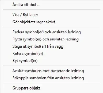
When you right-click on a symbol, conductor or text, a selection of functions specific to the selected item is displayed. For example, you can choose to connect the symbol to a passing wire.
Create your own luminaires
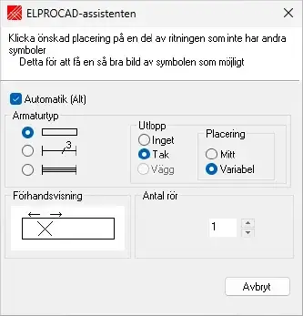
When you select the “Create your own luminaires” function, a preview appears in the ELPROCAD wizard showing how the luminaire will look before you draw it into the drawing. You can then easily insert the luminaire via clear icon menus.
Center symbols
The program also helps you to center symbols in a room.
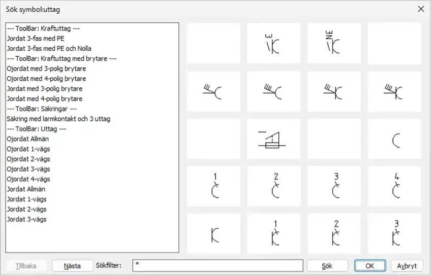
Search symbol
To quickly find a symbol in ELPROCAD Plan, there is a search function where you can enter a search string, for example sockets. The search result is then displayed in an icon menu, where all symbols containing the word socket are presented.
You can then choose to either directly insert the desired symbol or open the toolbar where the symbol is located.
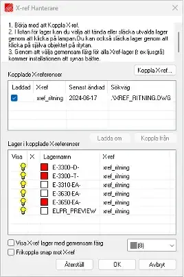
Using X-ref
Using an architectural drawing such as X‑ref is a very powerful and flexible way to draw the installation. The advantage of working with X‑ref is that the entire architectural drawing is treated as a single object, which prevents the drawing from being accidentally changed or damaged when drawing the installation. As the architectural drawing is handled as a separate DWG file, it can be easily updated when needed. Simply put, you put a transparent sheet on top of the architectural drawing, where you draw the installation.
The X‑ref Manager dialog box in ELPROCAD Plan makes it possible to hide unwanted layers and set a common color for the remaining layers, without affecting or changing the original architectural drawing.
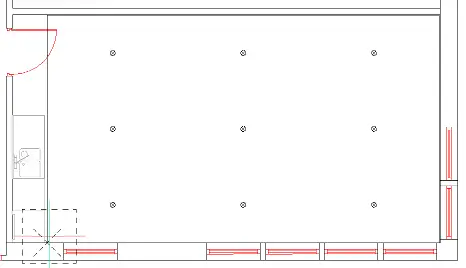
Matrices
ELPROCAD Plan helps you create neat installations using a matrix function. You can either specify the number of symbols to fit within a certain area or specify a fixed distance between symbols. The program then places as many symbols as will fit on the surface with the specified distance between them.
You can also draw

Central specification, group list
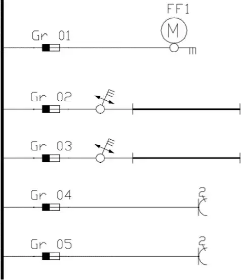
Single line diagram
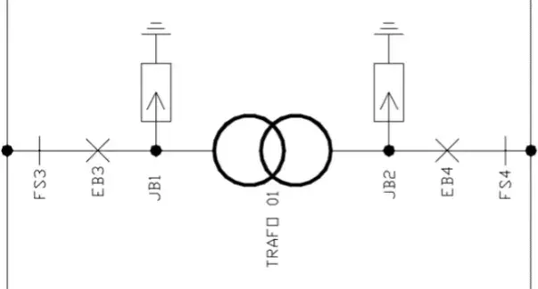
Overview diagram, main line diagram
Quantity report
When you’ve reached the stage in your project where it’s time to create a quantity report, it’s just a click away. The report analyzes what you have drawn and generates a clear report with neatly arranged columns showing quantities, designations and a range of other properties. Of course, information from the drawing header is also included, such as the drawing name, revision, sheet number, person responsible, date and more.
You also have the flexibility to create the report based on the entire drawing, only the objects that are visible, or those that are highlighted. The report is exported to an Excel report template included with the program but can be saved in a variety of formats, including tab-delimited .txt, and semicolon-delimited .csv. This allows you to choose the format that best suits your needs for further processing and analysis.
Online help
Although the program is very easy to use, you will always need help at some point. Online help is provided by the ELPROCAD Assistant, which provides instructions on what to do once you have selected a symbol or command.

Not sure what you need?
Contact our sales department for help and guidance on our different programs and licensing options.
Powerful simplicity
ELPROCAD gives you complete control, while being easy to use and efficient. Maximize your productivity and precision today.